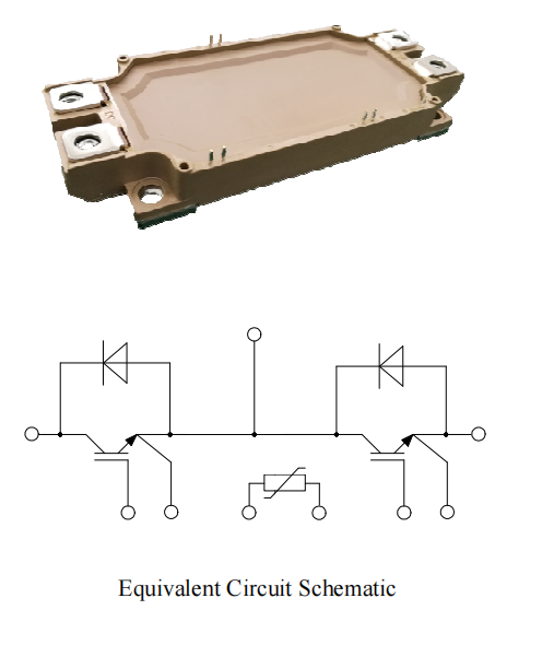
IGBT Module YZPST-450B170E53
3 year agoIGBT Power Module YZPST-450B170E53
Applications
Inverter for motor drive
AC and DC servo drive amplifier
UPS (Uninterruptible Power Supplies)
Features
Low Vce(sat) with SPT+ IGBT technology
Vce(sat) with positive temperature coefficient
Including fast & soft recovery anti-parallel FWD
High short circuit capability(10us)
Low inductance module structure
Maximum junction temperature 175C

Absolute Maximum Ratings
|
Parameter |
Symbol |
Conditions |
Value |
Unit |
|
Collector-Emitter Voltage |
VCES |
VGE=0V, IC =1mA, Tvj=25C |
1700 |
V |
|
Continuous Collector Current |
IC |
Tc=100C |
450 |
A |
|
Peak Collector Current |
ICRM |
tp=1ms |
900 |
A |
|
Gate-Emitter Voltage |
VGES |
Tvj=25C |
±20 |
V |
|
Total Power Dissipation (IGBT-inverter) |
Ptot |
Tc=25C Tvjmax=175C |
3260 |
W |
IGBT Characteristics
Turn-on Delay Time
td(on)
IC =450 A
VCE = 900 V
VGE = ±15V
RG = 3.3Ω
Tvj=150C
515
ns
Rise Time
tr
200
ns
Turn-off Delay Time
td(off)
730
ns
Fall Time
tf
430
ns
Energy Dissipation During Turn-on Time
Eon
175
mJ
Energy Dissipation During Turn-off Time
Eoff
130
mJ
SC Data
Isc
Tp≤10us,VGE=15V,
Tvj=150C,Vcc=1000V,
VCEM≤1700V
1450
A
Parameter
Value
Unit
Symbol
Conditions
Min.
Typ.
Max.
Gate-emitter Threshold Voltage
VGE(th)
VGE=VCE, IC =24mA,Tvj=25C
5.4
6.2
7.4
V
Collector-Emitter Cut-off Current
ICES
VCE=1700V,VGE=0V, Tvj=25C
1
mA
Ic=450A,VGE=15V, Tvj=25C
2.4
2.75
V
Collector-Emitter
VCE(sat)
Ic=450A,VGE=15V, Tvj=125C
2.8
V
Saturation Voltage
Ic=450A,VGE=15V, Tvj=150C
2.9
V
Gate Charge
G
2.7
uC
Input Capacitance
Cies
30
nF
Output Capacitance
Coes
VCE=25V,VGE =0V,
1.65
nF
Reverse Transfer Capacitance
Cres
f=1MHz, Tvj=25C
1.08
nF
Gate-Emitter leakage current
IGES
VCE=0 V, VGE=20 V, Tvj = 25C
400
nA
Turn-on Delay Time
td(on)
510
ns
Rise Time
tr
IC =450 A
180
ns
Turn-off Delay Time
td(off)
VCE = 900 V
620
ns
Fall Time
tf
VGE = ±15V
185
ns
Energy Dissipation During Turn-on Time
Eon
RG = 3.3Ω
126
mJ
Energy Dissipation During Turn-off Time
Eoff
Tvj=25C
89
mJ
Turn-on Delay Time
td(on)
512
ns
Rise Time
tr
IC =450 A
190
ns
Turn-off Delay Time
td(off)
VCE = 900 V
712
ns
Fall Time
tf
VGE = ±15V
350
ns
Energy Dissipation During Turn-on Time
Eon
RG = 3.3Ω
162
mJ
Energy Dissipation During Turn-off Time
Eoff
Tvj=125C
125
mJ
Diode Characteristics
| Parameter | Value | Unit | ||||
| Symbol | Conditions | Min. | Typ. | Max. | ||
| Diode DC Forward Current | IF | Tc=100C | 450 | A | ||
| Diode Peak Forward Current | IFRM | tp=1ms | 900 | A | ||
| IF=450A,Tvj=25C | 1.85 | V | ||||
| IF=450A,Tvj=125C | 1.92 | V | ||||
| Forward Voltage | VF | IF=450A,Tvj=150C | 1.9 | V | ||
| Recovered Charge | Qrr | IF =450 A | 110 | uC | ||
| VR=900V | ||||||
| Peak Reverse Recovery Current | Irr | -diF/dt =2500A/us | 348 | A | ||
| Reverse Recovery Energy | Erec | Tvj=25C | 64.2 | mJ | ||
| Recovered Charge | Qrr | IF =450 A | 160 | uC | ||
| VR=900V | ||||||
| Peak Reverse Recovery Current | Irr | -diF/dt =2500A/us | 394 | A | ||
| Reverse Recovery Energy | Erec | Tvj=125C | 94.4 | mJ | ||
| Recovered Charge | Qrr | IF =450 A | 176 | uC | ||
| VR=900V | ||||||
| Peak Reverse Recovery Current | Irr | -diF/dt =2500A/us | 410 | A | ||
| Reverse Recovery Energy | Erec | Tvj=150C | 103.2 | mJ | ||
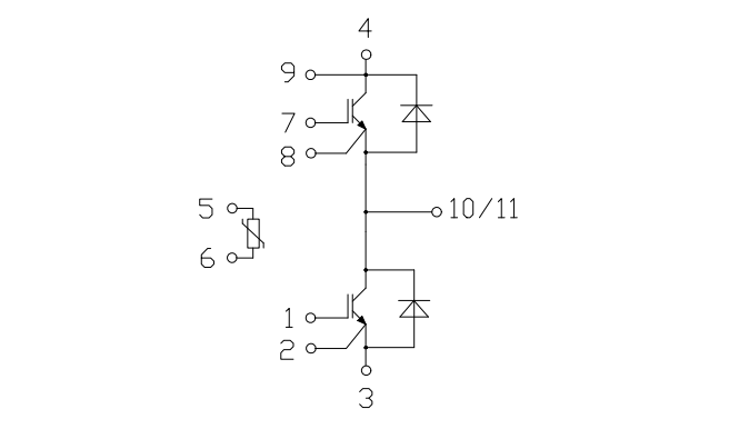
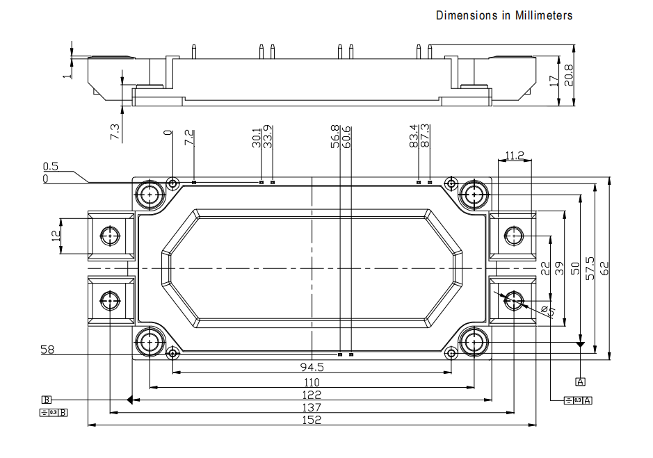
Circuit Diagram


Similar Video Recommendation
You May Also Like
If you are interested in the product, contact Bossgoovideo.com for more information
- *To:
- YANGZHOU POSITIONING TECH CO., LTD.
- *Message:
-
Submit
Main Product:
Semiconductor Triac ,
Semiconductor Thyristor,
Semiconductor Module,
Power Diode,
Silicon Transistor,
Bridge Rectifier
You May Also Like


